How to Ensure Accurate Testing with the GT-RA02 BFE Tester

How to Ensure Accurate Testing with the GT-RA02 BFE Tester

The GT-RA02 Mask Bacterial Filtration Efficiency Tester is an advanced device specifically designed to accurately measure the bacterial filtration capacity of masks. Its efficient and reliable testing process makes it the preferred tool for mask manufacturers, research institutions, and quality testing departments. This article will detail the operation steps of theMask Bacterial Filtration Efficiency (BFE) Tester, helping you conduct testing efficiently and safely.


1. Preparation Stage
Before conducting any tests, users need to be well-prepared. First, perform a safety check on the Mask Bacterial Filtration Efficiency (BFE) Tester to ensure it is stable and securely connected, with a safe power supply. Next, prepare the experimental materials, including standard petri dishes, bacterial suspension, and the Andersen sampler. Add the specified reagent to the petri dishes and install the Andersen sampler in sequence to ensure all materials are ready before starting the experiment. Additionally, ensure that the operating environment is sterile to avoid any potential contamination.

2. Equipment Startup and Disinfection
Starting the Mask Bacterial Filtration Efficiency (BFE) Tester is a critical step in the testing process. Users need to connect the power line and air compressor, turn on the air compressor, and set the air pressure to 0.2Mpa. After starting the equipment, turn on the control panel power, and sequentially start the fan, lighting, and UV lamp for disinfection, with a suggested disinfection time of no less than 30 minutes. During disinfection, wear gloves and prepare the bacterial suspension, petri dishes, and sampler. After disinfection, quickly place the experimental materials in the safety cabinet to maintain a sterile environment.

3. Testing Operation and Data Processing
Once preparation and disinfection are complete, users can proceed to the formal testing phase. Open the Andersen sampler, quickly place the test samples and petri dishes inside, and clamp them in sequence, ensuring the lid of the petri dish is inverted to prevent microbial contamination. In the parameter settings, users need to set the relevant testing and disinfection parameters, then click "Start" to enter the equilibrium stage. Once fog is observed, confirming the device is stable, the formal test can begin. After the test is completed, the system will automatically conduct air cleaning. Users should retrieve the petri dishes and incubate them in a biochemical culture cabinet at a constant temperature of (37±2)℃ for 24-48 hours, and then process and analyze the data according to the standard test methods.

With our GT-RA02 Mask Bacterial Filtration Efficiency Tester, you can not only meet industry standards but also gain the trust of your customers. Let us work together to provide you with professional solutions.

How to Operate the Semi-Automatic Ventilate Quick Constant Temperature Oven GT-A37

How to Operate the Semi-Automatic Ventilate Quick Constant Temperature Oven GT-A37

The Semi-Automatic Ventilate Quick Constant Temperature Oven GT-A37 is a powerful and efficient tool designed for precision drying and constant temperature testing. Specifically tailored for textile applications, it is capable of determining moisture regain in various fibers and textiles such as cotton, silk, fur, and synthetic fibers. This guide will walk through each step involved in the proper setup and use of the GT-A37 Constant Temperature Oven, as well as outline its key features and benefits.

Overview of the Semi-Automatic Ventilate Quick Constant Temperature Oven GT-A37
The GT-A37 Constant Temperature Oven is essential in textile and material science industries for rapid, accurate moisture analysis. It complies with standards like GB/T9995-1997, ISO2060/6741, and ASTM D2654, ensuring reliable, globally recognized results.


Step-by-Step Operation of Constant Temperature Oven
Here is a detailed guide on how to operate the emi-Automatic Ventilate Quick Constant Temperature Oven, from setup to data collection and result calculation.

Step 1: Setup and Initialization
To begin, ensure that all power sources are activated. Turn on the main power, the screen, and the balance scale to get started.

Power Activation: Ensure that the main power source and individual power switches for the machine, control screen, and electronic balance are switched on.

Temperature Setting:Use the control panel to set the test temperature. For moisture regain testing, set the temperature to 105°C by pressing the up and down buttons on the screen. The green display shows the set temperature, while the red display shows the real-time temperature.

Workstation Selection: On the control screen, select the workstations to be used. For instance, if using workstations 1 and 2, mark them with a check (√) and uncheck the remaining stations (3-8). Save these selections before moving to the next step.

Step 2: Sample Preparation and Weight Input
After the setup, the next step is to prepare the samples, weigh them, and input the data for precise monitoring during testing.

Bucket and Sample Weighing: For each sample, start by weighing the corresponding bucket. Select the specific bucket on the screen, place it on the electronic balance, zero the balance, and weigh it. Enter this weight by clicking “Numeric keyboard” on the control screen. Once the bucket weight is recorded, place it in the designated workstation on the turntable.

Sample Weighing: Weigh each sample individually on the balance, entering the initial weight into the control system by selecting the appropriate sample number and using the numeric keyboard. Place each sample inside the corresponding bucket.

Data Saving: Once both bucket and sample weights are recorded, click "Save Parameters" to ensure all data is securely stored in the system.

Step 3: Testing and Results Recording
With the samples prepared, begin the testing phase and monitor the progress until moisture levels stabilize.

Ventilation and Test Start:Open the ventilation outlet before starting the test. Press the “Start” button and record the start time. Let the test run for a set time (typically 25 minutes), then press "Pause" and close the ventilation outlet after a one-minute wait.

Weight Monitoring During Testing: Reconnect the balance scale to check sample weight changes. Position each bucket under the balance using the turntable controls, measure the current weight, and read the data. This step can be repeated periodically as necessary until the sample weight stabilizes.

Final Weight Confirmation and Data Analysis: Once the samples reach a constant weight, click “Count” on the control screen to calculate the moisture regain results. Review the final data in the "Statistical Reports" section for a summary, and print the results for record-keeping.


Key Features of emi-Automatic Ventilate Quick Constant Temperature Oven

Feature
Detail
Minimal thermal inertia heating
Improved temperature stability and accuracy
Forced convection, hot air drying
Enhanced drying speed and energy efficiency
Airflow control during weighing
Reduced air disturbance for accurate measurements
LED temperature display
Clear readings with high precision
7-inch touchscreen interface
User-friendly control with vibrant display quality
Windows CE operating system
Intuitive, efficient human-computer interaction


Benefits of Using the Constant Temperature Oven for Textile Testing
The Constant Temperature Oven is a robust tool that significantly improves testing efficiency. Its high precision, coupled with advanced features like forced convection and automatic airflow control, ensures that textile manufacturers receive accurate moisture data quickly. This accuracy is crucial for maintaining quality control in industries that rely on textile moisture consistency, like apparel and upholstery manufacturing.

ISO 24266 Method A Test methods for Whole Shoes Flexing

ISO 24266 Method A: Test methods for Whole Shoes Flexing

In the quality assessment system of footwear products, the folding resistance test is an important indicator of the service life and wearing comfort of shoes.

By following the ISO 24266 Method A standard, manufacturers can ensure that their products are both durable and reliable. Our GT-KA01-2 Whole Shoe flexing Tester meets this standard.
Whole Shoes Flexing Tester

Comprehensive Testing Methods


Shoes Flexing tester is mainly applicable to testing the flexing resistance of various types of finished shoes, including but not limited to:

  • Athletic shoes: to assess the effects of repeated bending on the sole and upper during long-term sports activities
  • Casual shoes: testing the durability under daily wear conditions
  • Work shoes: to test fatigue resistance under special working conditions
  • Safety shoes: to ensure long-term reliability in industrial environments

And determine its flexing resistance or indicating the cracks of shoe or shoe sole through reciprocating flexing movements under the specified angle and frequency.


Whole Shoes Flexing Tester


Compliance Advantages


Compliance with the ISO 24266 Method A standard offers many benefits:
  • Improved product quality: Compliance with ISO 24266 Method A allows manufacturers to produce footwear that meets high quality benchmarks, resulting in increased customer satisfaction.
  • Improved market competitiveness: Products that comply with international standards are more likely to be recognized in the global marketplace, thereby improving brand competitiveness.
  • Reduced returns and complaints: Durable footwear reduces the likelihood of returns and customer complaints, saving costs and maintaining brand reputation.

The Role of Printing Prototype Machine in Synthetic Fiber Dyeing Processes

The Role of Printing Prototype Machine in Synthetic Fiber Dyeing Processes

In the textile industry, synthetic fibers have gained significant traction due to their versatility, durability, and cost-effectiveness. However, achieving consistent dyeing results for synthetic fibers can be a challenging process. The Printing Prototype Machine GT-D25 plays a crucial role in optimizing dyeing processes for synthetic fibers, ensuring precision, efficiency.

GESTER delves into the importance of the Printing Prototype Machine in synthetic fiber dyeing, exploring its features, applications, and benefits.

Printing Prototype Machine

Understanding the Printing Prototype Machine GT-D25
The Printing Prototype Machine GT-D25 is a universal tool used extensively in printing and dyeing laboratories. Its sophisticated design and cutting-edge features allow for accurate simulation of large-scale printing and dyeing processes on a smaller scale.

Key Features and Their Role in Dyeing Processes
The Printing Prototype Machine boasts several advanced features that enhance its utility in dyeing applications:

1. Electromagnet-Powered Roller Squeegee:
The use of an electromagnet-driven squeegee ensures smooth, consistent application of dye across the fabric. This feature is crucial for synthetic fibers, which often require uniform dye distribution to avoid patchiness.

2. Adjustable Scraping Strength:
The ability to freely set scraping strength offers precise control over dye penetration, making it easier to manage the varying absorption properties of synthetic fibers like polyester, nylon, and acrylic.

3. Variable Speed Control:
Frequency conversion technology allows users to adjust scraping speed, ensuring compatibility with different fabric types and dye viscosities. This versatility is vital for achieving optimal results during the color matching process.

4. One-Time and Circulate Scraping Modes:
These modes provide flexibility for different testing requirements. For initial color testing, a one-time scrape may suffice, while circulate scraping ensures thorough dye application for more detailed evaluations.

5. Customizable Scraping Distance:
The ability to set scraping distances allows for precise control over the application area, making it easier to replicate specific patterns and designs during the printing strike-off process.

Applications in Synthetic Fiber Dyeing
Synthetic fibers are known for their durability and versatility, but their dyeing process often involves complex challenges such as poor dye affinity, uneven coloration, and dye migration. The Printing Prototype Machine GT-D25 addresses these issues through its ability to replicate real-world conditions and test various dyeing parameters.

1. Printing Strike-Off Process
The strike-off process is a preliminary step in fabric printing, where small samples are created to evaluate patterns, colors, and dye penetration. GESTER Printing Prototype Machine excels in this area by offering precision and repeatability, ensuring that the samples closely represent the final production outcomes. For synthetic fibers, which require careful handling to prevent dye migration, the machine’s advanced controls are invaluable.

2. Dye Color Matching

Achieving accurate color matching is particularly challenging with synthetic fibers due to their resistance to dyes. The Printing Prototype Machine allows for meticulous testing of dye formulations and application techniques, enabling technicians to perfect the process before scaling up to full production. Its customizable scraping settings ensure that even the most stubborn synthetic materials can achieve vibrant, uniform colors.


Challenges Addressed by GT-D25 in Synthetic Fiber Dyeing
Synthetic fibers often exhibit characteristics like hydrophobicity, which makes them resistant to water-based dyes. Additionally, their chemical structures may interact differently with dyes, leading to inconsistent results. The Printing Prototype Machine GT-D25 mitigates these challenges by enabling precise control over every aspect of the dyeing process, from dye application pressure to scraping speed and distance.

For example, when working with polyester—a common synthetic material—the machine’s adjustable scraping strength and variable speed control help ensure that the dye penetrates evenly without causing damage to the fabric. Similarly, for nylon, which is prone to color bleeding, the circulate scraping mode allows for a more controlled application that minimizes these issues.

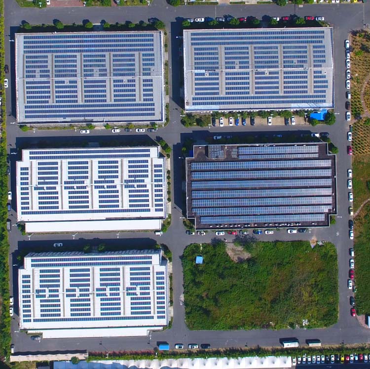
Photovoltaic application sites

  On October 12, the National Development and Reform Commission issued the "Notice of the National Development and Reform Commission on Further Deepening the Market-oriented Reform of Coal-fired Power Generation On-grid Tariffs" (Fagai Price [2021] No. 1439), proposing to adjust coal-fired power generation transaction prices up and down The scope is no more than 20% of the benchmark electricity price, and it is clear that the document will be implemented on October 15. The increase in electricity prices is not good news for industrial and commercial companies, but it is indeed good news for photovoltaic companies. PV installation has now become a rigid demand. Distributed photovoltaics have different application scenarios in many places. Specific examples illustrate:

1.  Hosptial

  As a public service organization with high energy consumption, hospitals face great pressure in the future energy saving, emission reduction and consumption reduction work. The installation of photovoltaic power stations on the roof of the hospital actively explores the construction and development of green hospitals, and promotes the concept of green buildings and energy saving. The scientific application of consumption reduction technology is particularly important.

2. School

The school has the advantages of installing photovoltaic power plants: ① The power station is built on the roof of the school, which is a large science popularization base; ② The school has a wider roof, good structure and stable power consumption; ③ The school has stable operation, clear property rights, and relatively financing easy.

3. Highway

  Photovoltaic + highway has been widely used, making full use of the space resources of the highway, realizing the organic integration of photovoltaic power generation, transportation, energy saving and emission reduction, and road maintenance. Using highways as a new carrier of photovoltaic power generation led the new trend of the photovoltaic industry, created a new image of green highways, and laid a good foundation for the later smart highways. Photovoltaic is generally installed in the service area of the expressway, in the middle or on both sides of the road, in the tunnel or directly paved on the highway.

4. Industrial plant/park

  Industrial plants are the most widely used and most industrial and commercial projects. The installation of photovoltaic power plants in industrial plants can use idle roofs to revitalize fixed assets, save peak electricity bills, and use surplus electricity to connect to the Internet to increase corporate income, and it can also promote energy conservation and emission reduction, and generate a good society. benefit.

  In order to improve the reliability of lightning protection of distributed photovoltaic power plants and the safety of the human body, protective measures must be taken against voltage transients and surges. Jinli Electric’s photovoltaic surge protection devices can be offered.

What are the components of the intelligent lightning protection system? What are the advantageas?

The intelligent lightning protection system introduces the concept of intelligence into the lightning protection system, integrating the three major modules of "intelligent SPD online monitoring" + "lightning warning online monitoring" + "ground resistance online monitoring". It uses modern microcomputers and communication technologies to collect monitoring and collected data, so that lightning protection can be predicted in advance, from the previous passive protection to active protection. At the same time, it is more convenient for lightning protection product maintenance and management to be more timely, more convenient and more effective. On the basis of the above functional modules, the intelligent lightning protection monitoring system also has a graphical operating system that integrates lightning protection, operation monitoring, equipment management, report analysis, historical records, warning and user management.

SPD online monitoring: real-time monitoring of the working status of theSPD (such as leakage current, residual voltage, aging degree) to ensure its effective operation.

Ground resistance online monitoring: Continuously measure the resistance value of the grounding system to detect poor grounding or corrosion problems in time.

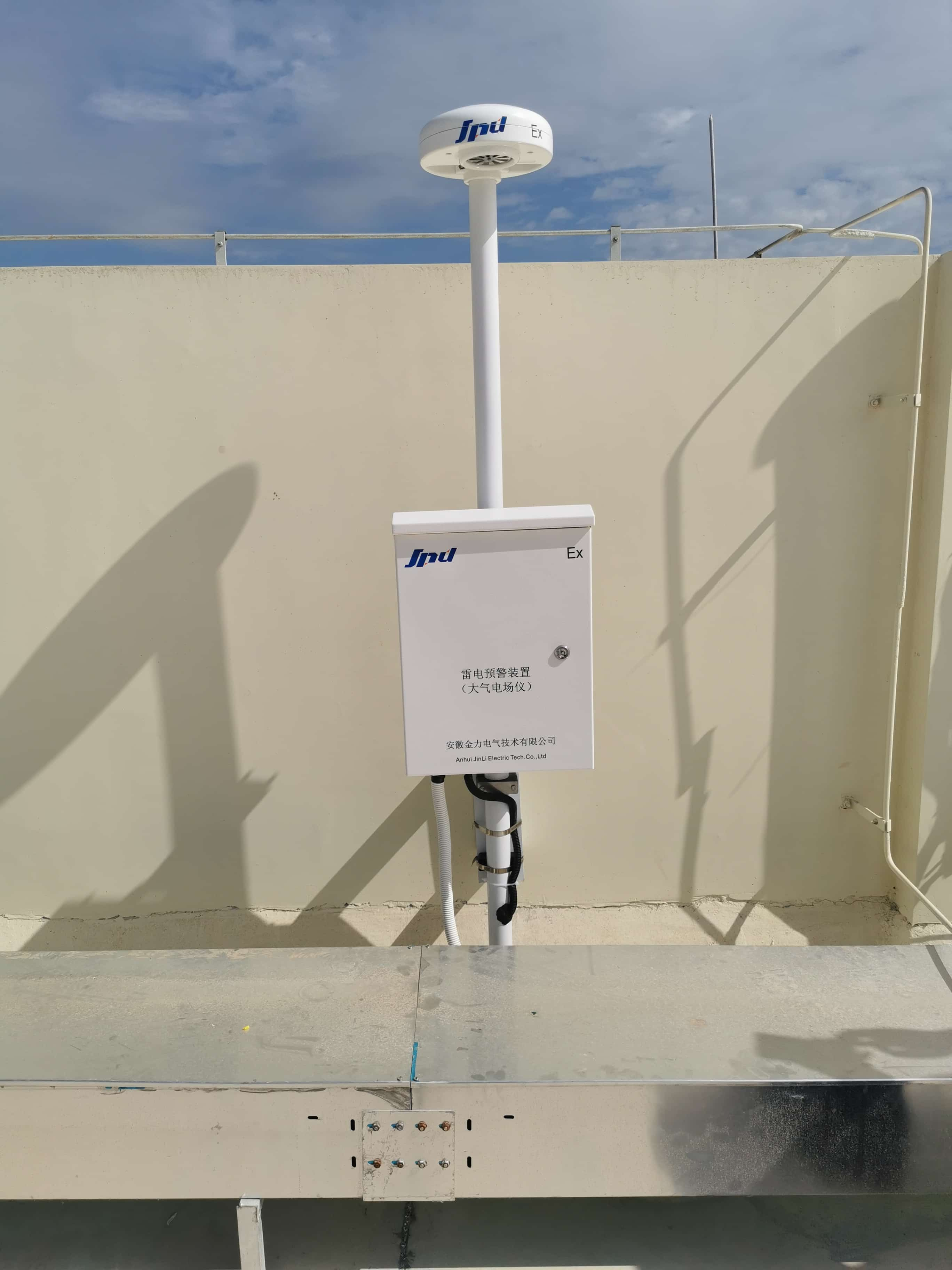
Lightning warning online monitoring : Combines meteorological data with electric field sensors to predict lightning activity and issue warnings in advance.

lightning protection warning system

Advantages analysis:

1. Real-time monitoring and active early warning

Limitations of traditional lightning protection: Relying on manual regular inspections (such as once a year), sudden problems may be missed (such as instantaneous failure of SPDs and damage to the grounding system after a lightning strike).

Advantages of intelligent systems

1)Real-time feedback of SPD status: Once the leakage current exceeds the standard or the residual voltage is abnormal, the system will automatically alarm and generate a maintenance work order.

2) Dynamic monitoring of ground resistance: When the ground resistance value exceeds the threshold, an alarm is triggered immediately to ensure safe discharge of current during lightning strike.

3) Lightning warning accuracy: predict lightning activities 30 minutes to 1 hour in advance togain protection time for key facilities (such as airports and data centers).

2. Data-driven preventive maintenance

Traditional method: Maintenance relies on experience and judgment, and it is difficult to predict the life of equipment.

Intelligent system: Through long-term data accumulation, analyze the aging rules of SPDs and the changing trends of grounding resistance, and formulate targeted maintenance plans.

Case: A chemical plant discovered the SPD leakage current in a certain area increased year by year through monitoring data,andavoided the paralysis of the production line caused by lightning strike after replacingthe spd in advance.

3. Improve safety and reduce losses

Direct benefits: Reduce the risk of fire and equipment damage caused by lightning strikes; protect sensitive equipment (such as medical instruments and servers) to avoid data loss or business interruption.

Indirect benefits: Reduce insurance claims and accident compensation costs; enhance corporate safety image and increase customer trust.

4. Reduce long-term operation and maintenance costs

Traditional model cost: Manual inspection is expensive, and repair costs for sudden failures are high.

Intelligent system cost: The initial investment is higher, but the frequency of failures can be reduced in the long term through preventive maintenance.

Data shows: after a communication base station adopted intelligent lightning protection, the average annual maintenance cost was reduced by 40% and the failure rate decreased by 70%.

Necessity analysis

1. Coping with the high sensitivity of modern equipment

As the integration of electronic devices increases, their ability to withstand surges decreases significantly. Traditional lightning protection can only protect against direct lightning strikes, whileintelligent systems can fully resist threats such as inductive lightning and operational overvoltage.

2. Adapt to complex environment needs

Special places: such as oil storage tank areas, data centers, high-speed rail stations, etc., have extremely high requirements for lightning protection reliability, and the real-time monitoring and early warning functions of the intelligent system are indispensable.

Geographic factors: Areas with high incidence of lightning (such as tropical and mountainous areas) require more precise protection strategies. Smart systems can optimize lightning protection layout through data analysis.

3. Promotion of regulations and standards

International standard: IEC 62305 explicitly requires continuous monitoring of lightning protection systems.

Domestic policy: GB/T 21431-2015 "Technical Specifications for Testing of Lightning Protection Devices for Buildings" encourages the use of online monitoring technology.

Industry requirements: Electricity, communications, transportation and other fields will gradually incorporateintelligent lightning protection into mandatory safety standards.

4. The inevitable trend of digital transformation

The advancement of concepts such as smart cities and Industry 4.0 requires the simultaneous intelligentization of infrastructure and safety management. As the core link of safety assurance, the lightning protection system must be integrated with the digitalization process.

SPD


What are the requirements for the installation of the connecting wires at both ends of the SPD?

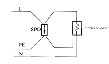
  Regardless of TN system or TT system, the connection wires at both ends of the SPD connected to the live conductor and PE line should be short and straight. The IEC standard stipulates that the total length of the SPD connection wire should not exceed 0.5m. This is because the lightning impulse current has high-frequency characteristics, and the lightning impulse overvoltage applied to the protected electrical equipment is the residual voltage on the SPD plus the Ldi/dt high-frequency voltage drop on the connection wire (L is the inductance of the wiring at both ends of the SPD, which is proportional to the length of the connection wire, and di/dt is the steepness of the change of the lightning impulse current). The residual voltage of the SPD is determined by the product performance and cannot be changed, while the Ldi/dt on the connection wire can be reduced in the design of the electrical device by reducing the length of the connection wire, that is, reducing the inductance. Therefore, it is best to install the SPD directly between the live conductor busbar and the PE busbar of the distribution box to minimize the length of the connection wire. Now some SPD products have been made according to the modulus of the miniature circuit breaker in the distribution box so that they can be directly installed in the distribution box, which is very beneficial to shorten the length of the SPD connection wire.


  If this is difficult to do for some reason, the SPD can be installed elsewhere. In this case, it is best to use a "V" connection method for the SPD, as shown in Figure 1. The length of the SPD connection line in the figure is almost zero, but this connection method will encounter some difficulties and inconveniences in actual construction.

SPD


Figure 1 V-shaped connection in SPD connection


Why do need to install SPD after installing lightning rod? What is the core difference between SPD and lighting rod?

1. The role and limitations of lightning rods

Intercepting direct lightning strikes: Lightning rods attract lightning through tip discharge and safely conduct lightning current into the earth through down conductors, protecting building structures from damage by direct lightning strikes.

Limited protection range: The protection range of a lightning rod depends on its height and rolling ball radius, and it cannot cover all possible lightning strike paths.

No protection against induced lightning and surges: When lightning strikes occur, even if the lightning rod successfully conducts the lightning current, the strong lightning current will still induce transient overvoltage (surge) in nearby wires (such as power lines and signal lines). These surges can enter the building through the lines, damage electronic equipment, and cause electrical fires.

2. The core role of SPD

Discharge surge energy: SPD limits transient overvoltage in the line to a safe level through rapid response (nanosecond level) and discharges excess energy to the ground.

Protect sensitive equipment: Prevent power surges from damaging computers, home appliances, communication equipment, etc. through power and communication lines (even if the building is not directly struck by lightning).

T1 SPD: Installed at the incoming line end of a building (such as the main distribution cabinet) to deal with high-energy surges introduced by direct lightning strikes.

T2 SPD: Installed in the distribution cabinet or at the front end of the equipment to further limit the residual pressure and protect the terminal equipment.

3. Collaborative protection of lightning rod and SPD

External lightning protection + internal lightning protection:

Lightning rod (external lightning protection): responsible for intercepting direct lightning strikes and protecting the building structure.

SPD (internal lightning protection): responsible for eliminating induced lightning and surges, protecting electrical systems and equipment.

Actual scenario example

The lightning current enters the ground through the down conductor, but it will generate an induced surge in nearby conductors. Without SPD, power surges may enter the room along the power lines, burning out electrical appliances or causing fires. When lightning does not directly strike the target building: when lightning strikes the nearby ground, buildings, or discharges between clouds, the changing electromagnetic field induces overvoltage on the power grid conductor, and SPD can protect against such surges.

surge protection device

Why do we need to conduct regular lightning protection inspections on buildings?

1. Required bythe standard

1)Required by the standard, the national standard is mandatory

GB 50057 Design code for protection of Structures against lightning:

Article 4.5.4 clearly requires that lightning protection devices should be inspected regularly, generally once a year;toflammable and explosive places, the inspection cycle needs to be shortened to once every six months.

Article 6.4.3 stipulates that the grounding resistance value must meet the design requirements (usually ≤10Ω, ≤4Ω in important places), otherwise rectification is required.

2)Industry norms and legal basis

"Work Safety Law": requires enterprises to fulfill their primary responsibility for lightning protection safety, and those who fail to conduct regular inspections and cause accidents must bear legal responsibility.

IEC 62305 series of standards: The International Electrotechnical Commission emphasizes that lightning protection systems must be periodically tested to ensure their effectiveness, especially in areas with high incidence of lightning.

2. Actual on-site requirements

1)Prevent direct damage from lightning strikes

Fire and explosion risks: Lightning strikes can directly ignite flammable materials in places such as gas stations and chemical plants. Testing ground resistance and equipotential bonding can eliminate potential spark discharges.

Structural safety: Corrosion or breakage of lightning arresters may result in the inability to safely discharge lightning current, causing damage to buildings.

2)Protect equipment and systems

Vulnerability of electronic equipment: Lightning strikes or power surges can damage precision equipment such as servers and medical devices. Testing SPD performance (such as residual voltage and leakage current) can ensure that it effectively limits voltage.

Power system stability: Detection of shielding and wiring compliance of distribution lines can reduce the impact of lightning-induced overvoltage on the power grid.

3)Adapt to environmental changes

Facility aging: Grounding corrosion and SPD component degradation are inevitable over time, and regular inspections can help replace failed components in a timely manner.

Site renovation: Building expansion or use change may damage the original lightning protection system, requiring reassessment of lightning protection level and adjustment of configuration.

4)Necessary needs for special places

Communication base stations and data centers: The high reliability of the lightning protection system must be ensured to avoid business interruption and data loss.

Hospitals and airports: Lightning protection failure may threaten life safety, and detection is a core measure to ensure the uninterrupted operation of critical facilities.

3. Undetected potential risks

1)Legal liability and economic compensation

If a lightning strike accident occurs due to failure to detectit, the company may face administrative penalties, civil compensation or even criminal liability (such as major safety accident crime).

2) Hidden safety risks

For example, if the grounding resistance exceeds the standard but is not discovered, the current cannot be effectively discharged when lightning strikes, which may cause step voltage electric shock or equipment damage.

3) Shortened equipment life

The leakage current of an SPD that has not been detected for a long time will increase, which may accelerate aging and eventually lose its protective function, causing frequent equipment failures.

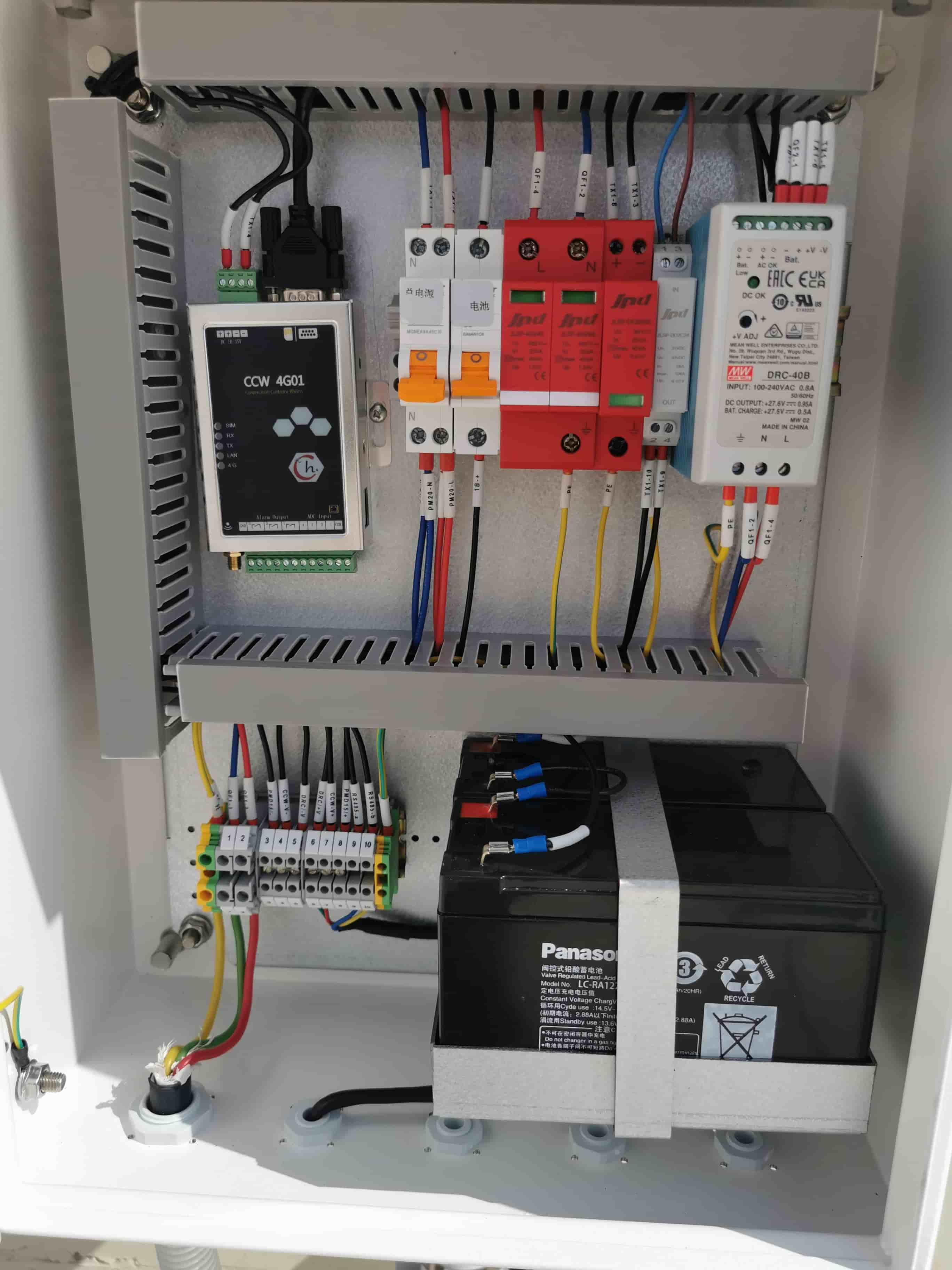
ac spd device

The Evolution and Future of Beverage Packaging Equipment

The beverage industry has come a long way since its inception, and so has the equipment that supports it. KOCO IMP/EXP CO., LTD has been at the forefront of beverage manufacturing for 25 years, leveraging our expertise to deliver high-quality products. As the industry evolves, so do we—embracing advancements in filling technology to meet the growing demand for efficient and sustainable beverage production.

Key Features of Modern Beverage Equipment

Today’s beverage equipment is designed for speed, precision, and versatility. Here’s what makes modern machines different:

High-speed operation: These machines are capable of processing thousands of packages per hour, maximizing productivity.

Precision filling: Ensures consistent product quality by accurately measuring and filling liquids.

Sanitary design: Stainless steel construction and easy-to-clean components ensure compliance with food safety standards.

Versatile use: Can accommodate a variety of packaging formats, including bottles, pouches, and cartons, ideal for a wide range of beverage types.


  • ketchup packing machine

    For the production of spout pouch liquid packaging.

  •    koyo sachet machine

    Used in sachet liquid packaging production.

  •    pouch packing machine 

    Used for pouch liquid packaging production.


ross-industry applications

Beverage packaging equipment is not limited to juice and soda. It is versatile and can be used for:

Beverage manufacturing: Ideal for juices, tea drinks, dairy products, and more.

Food Industry: For sauces, condiments, and other liquid products.

hemical Industry: Dishwashing liquids, laundry detergents, cleaners, etc.

Health-conscious market: Meeting the demand for fresh, organic, and nutritious beverages.


  • doypack

    For packaging juice, yogurt, jelly, laundry detergent, etc.

  • PE Plastic Film Roll Bag
    For packaging Sachet Water/Juice/Milk, etc.

  • Special-Shaped Bags
    For packaging juice, water, milk and other liquids.


Market Outlook and Trends

The market for automated beverage packaging solutions is booming, driven by consumer preferences for convenience and health. Here are the factors shaping the future:

Large-scale production: Equipment is trending toward larger capacities to optimize costs and meet large-scale production needs.

Smart technology integration: Modern machines feature IoT connectivity, real-time data monitoring, and AI-driven customization.

Sustainability focus: Innovations in eco-friendly packaging and energy-efficient operations are gaining traction.

Our Latest Innovations

At KOCO, we are committed to pushing boundaries. Our latest equipment combines advanced automation with a user-friendly interface to simplify operations while increasing efficiency. Whether you need a stand-alone juice packaging machine or complete juice treatment equipment, our team of experts will work with you to design the perfect solution for your business.

Conclusion

The beverage industry is rapidly evolving, and so is the technology that drives it. By investing in modern, versatile equipment, businesses can stay ahead of the curve while meeting consumer demands for quality and sustainability. Are you ready to change your beverage production? Let's build the future together!


Contact number: 0086-19159001917